3D printable D-shaft
September 2022
Imagine this: You want to design a 3D printable knob that fits on a standard EC11 rotary encoder with a flatted D-shaft. So you subtract the shape of the shaft, slice it, dice it, and let your favorite FFF printer do its magic. But alas, you might end up as disappointed as I did. Because even a tight fit quickly wears loose, to the point where the knob slides off when tilted. So I tried to come up with a design that better clamps onto the encoder.
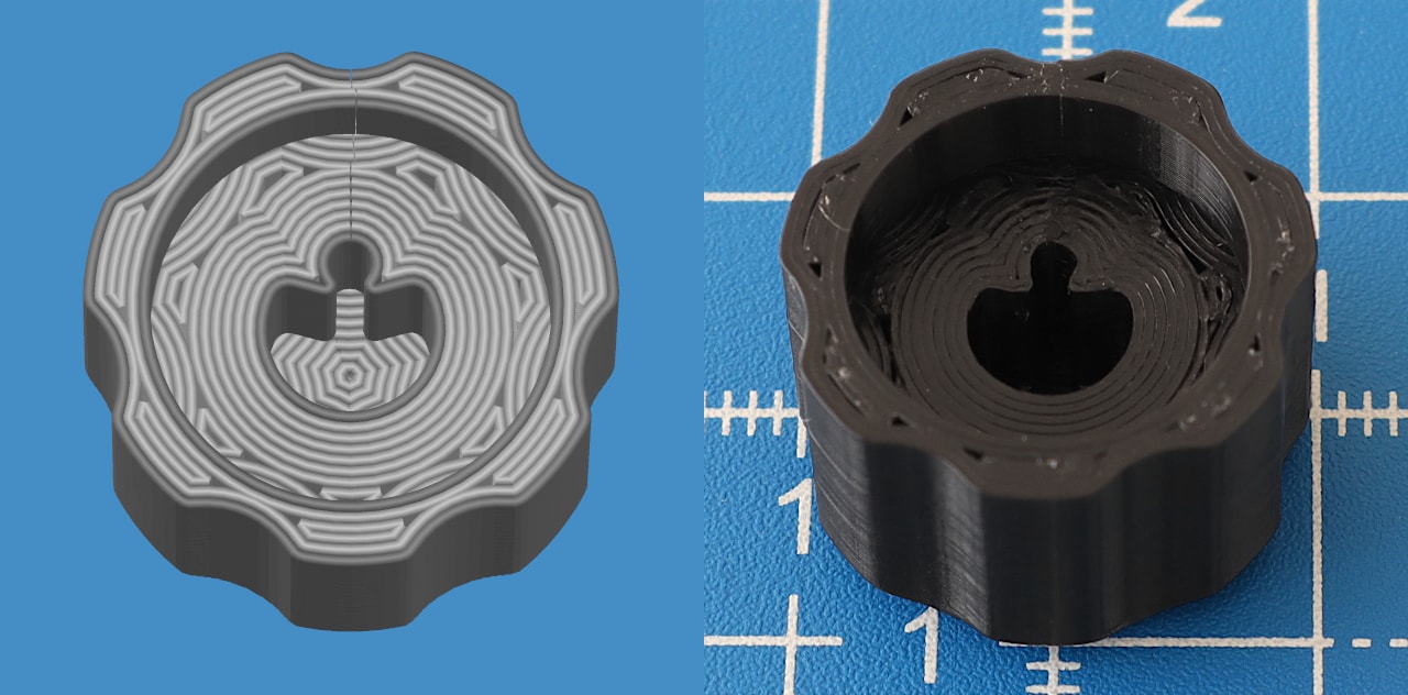
Injection molded knobs, like the Scrubber and Rubber knobs sold by Adafruit, may use prongs or ribs to press against the shaft. In those cases, the prongs end in sharp corners, which are difficult to print and potential weak points. Instead, I propose to transition the prongs into a circular notch, to produce a smooth perimeter that acts as a spring. At least in theory.
Construction
The programmatic construction of the shaft sketch is part of the Chrumm keyboard generator. For convenience, I have ported the code to a stand-alone Python script, which exports the sketches to DXF, via ezdxf. Along with some sample DXF and STL files, it is available here (54 KiB).
The code makes use of simple geometric primitives, such as vectors and rays. The following extracts should provide enough information to construct it in a more elegant way, in a proper CAD workflow, by someone who knows what they are doing.
shaftRadius = 6.2/2
acrossFlat = 4.35
prongRadius = 0.87/2
prongAngle = 15
relProngPitch = 1/3
relNotchSize = 2/3
The default parameters are based on test prints on a Prusa Mini, with PLA filament. The prong radius is intended for a layer height of 0.15mm, according to the Slic3r flow math.
flatY = acrossFlat - shaftRadius
flatX = (shaftRadius**2 - flatY**2)**.5
flatVertex = Vec(flatX, flatY)

prongX = flatX * relProngPitch
prongY = flatY + prongRadius
prongCenter = Vec(prongX, prongY)

notchRadius = prongX - prongRadius*(1 - relNotchSize)
notchHypot = prongRadius + notchRadius
notchOffset = (notchHypot**2 - prongX**2)**.5
notchCenter = Vec(0, prongY + notchOffset)
To reduce stress when the prongs are pushed back, their outer "hinge" corners are rounded as much as possible. To avoid any relevant interference, the hinge arc starts at the same position as the flatted corner vertex. The main challenge is to find the center of the arc.
To ensure a smooth transition, the arc must share a tangent with the shaft and the prong. Because the arc lies on a circle, the distance of its center to each tangent must be equal. Therefore, the center must lie on the bisector of the tangents. And because the arc shares a tangent with the shaft at the flat vertex, the arc center must also lie on the diagonal from the shaft center to the flat vertex.
flatDiagonal = Ray(Vec(), flatVertex)
shaftTangent = flatDiagonal.orthogonal(flatVertex)

prongDir = Vec.from_deg_angle(prongAngle)
prongOrtho = prongDir.orthogonal()
prongTouch = prongCenter - prongOrtho*prongRadius
prongTangent = Ray(prongTouch, angle=prongDir.angle)

hingeBisect = shaftTangent.bisectrix(prongTangent)
hingeCenter = flatDiagonal.intersect(hingeBisect)
hingeRadius = (hingeCenter - flatVertex).magnitude
Once the arc centers are established, all that remains is to find their start and end angles. Note that all arcs in DXF are counter-clockwise, so the prong arcs are reversed.
notchStart = (prongCenter - notchCenter).angle_deg
notchEnd   = 180 - notchStart
prongStart = 180 + notchStart
prongEnd   = 270 + prongAngle
hingeStart = hingeCenter.angle_deg
hingeEnd   =  90 + prongAngle
shaftStart = 180 - hingeStart
shaftEnd   = hingeStart