Hexagon holes for cheaper 3D prints
August 2022
Printing a large, flat surface with a FFF 3D printer does not just waste a lot of filament and print time, it also introduces the notorious risk of warping. A simple solution is to add holes to the surface. But in what shape, and what pattern? I could not find a lot of data on this subject, so I would like to share some of my own. It will not blow your socks off, but might be interesting nonetheless.
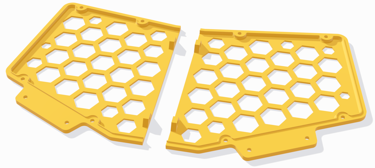
For the floor plate of the Chrumm keyboard, I tried to find a pattern that is not just cost effective, but also aesthetically pleasing. I ended up with a hexagon grid that is dynamically scaled to fit into an irregular border polygon.
Bestagons
Regarding the individual hole shape, an objective comparison is difficult, because the differences are small and easily distorted by printing parameters, such as the infill orientation. In general, the rounder the hole, the faster the print of its perimeter. A circle prints faster than a square of the same area, not just because it is proportionally shorter, but also because sharp corners slow down the print head. Conversely, round shapes do not tessellate well, and thus require more infill between the holes.
Unsurprisingly, I found that hexagons are indeed bestagons. With slightly rounded corners, they print almost as quickly as circles of the same area, without gratuitous infill. I got the best results with a corner radius between 0.5mm and 1mm.
Fill strategies
The big challenge was to dynamically fit a regular hexagon grid into the irregular shape of the floor plate. The following shows a few possible fill strategies.
I used the Prusa Slicer to determine the printing stats. Feel free to download the test files (132 KiB), along with the printer settings. For each strategy, the ideal grid offset was determined with a brute-force search, at a resolution of 1mm. The holes have a maximum diameter of 24mm, with a hole margin of 5mm. This size is somewhat arbitrary, but based on test prints, it is the largest hole size I'm comfortable with. Other use cases will require different values.
| Name | Holes | Area | Time | Filament |
| no-holes | 0 | 100% | 2h21m | 42.52g |
| inside | 24 | 56.4% | 1h47m | 24.40g |
| inside-small | 37 | 54.1% | 1h51m | 23.47g |
| cut-corners | 28 | 49.9% | 1h43m | 21.67g |
| scaled | 30 | 48.7% | 1h42m | 21.16g |
| scaled-small | 45 | 47.4% | 1h48m | 20.74g |
| cut-edges | 35 | 41.9% | 1h38m | 18.32g |
The most simple approach is to discard any hexagon that is not fully inside the border, though it will leave a lot of room toward the edge. A smaller grid can better approximate the border and thus save more filament. However, that also increases the print time.
Instead of discarding a hexagon entirely, it can be trimmed instead. Cutting off corners until the hole fits is a straight-forward improvement. Though the most cost effective result can be achieved by cutting each partially contained hexagon along the border edge. A boolean intersection, if you are so inclined. However, there is one major issue with the edge cut. I don't like the look of all the irregular, concave holes.
That's why I ended up with a solution where partially contained hexagons are scaled instead of trimmed. When all holes retain the same shape, the visual result is much more consistent. In terms of cost performance, it is not quite as good as the edge cut. But based on the rudimentary calculation from Prusa ($25.00/kg, $0.10/h), the difference is about 7 cents, which is fine by me.
Hexagon scaling algorithm
My implementation is not very efficient, but it should be reasonably correct. At least, it produces the intended result for my use case. The code can be found on GitHub.
We start with the border polygon. The bounding box of the polygon is filled with a trivial hexagon grid. The scaling is then performed per hexagon.
To avoid unnecessary calculations, we check if scaling is necessary at all. Measure the minimum distance of the hexagon center to each polygon segment. If the distance is greater than the outer radius of the hexagon, it must be either fully inside or outside the polygon. If the center is inside the polygon, we keep the hexagon as it is. If the center is outside, the hexagon is discarded.
If the distance to the polygon is too small however, then the hexagon must be scaled to fit. In that case, we need to consider two scale factors, for each hexagon corner c that is inside the polygon.
For each polygon vertex p that is inside the hexagon, consider a ray that starts at c and passes through p. This ray must intersect one of the hexagon segments at point i. With c as the scale center, we can scale the hexagon down by the factor ‖p-c‖ / ‖i-c‖ to exclude point p. The minimum of all these scale factors therefore excludes all polygon vertexes.
The figure shows that excluding the vertexes is not enough, as polygon segments may still intersect the hexagon. Consider a diagonal line segment from c to each non-neighbor corner d. If the diagonal intersects a polygon segment at point s, the scale factor to exclude the intersection point is ‖s-c‖ / ‖d-c‖. The minimum of these factors ensures that no diagonal is intersected by the polygon.
The smaller of both minimum factors is the best scale factor for the respective hexagon corner. We then choose the corner with the largest minimum factor to become the final scale center along with its scale factor, to get the largest hexagon that is fully inside the polygon. To avoid tiny holes, it is wise to use a lower threshold for the factor.
This is the current state of my implementation. Because each hexagon is scaled independently, some room for improvement remains. When two neighboring hexagons are scaled down, one could could take into account the space that is freed up by the other. Would the potential savings justify the required effort? Probably not.