Making a keyboard prototype
July 2020
For many years, I have used a Microsoft Ergonomic keyboard, because its sculpted shape is rather comfortable. However, it is rattly and bulky, with the arrow and numpad clusters getting in the way of the mouse real estate. As a result, I often subconsciously moved the keyboard leftward, ending up with a contorted typing posture.
In an effort to fix this issue, I found an enthusiastic open-hardware community that has come up with many interesting alternatives. Reading about all these home-grown projects encouraged me to make my own interpretation of an ideal mechanical keyboard, and to learn a thing or two about prototyping, soldering, and embedded programming in the process. The design files are available on GitHub.
Layout
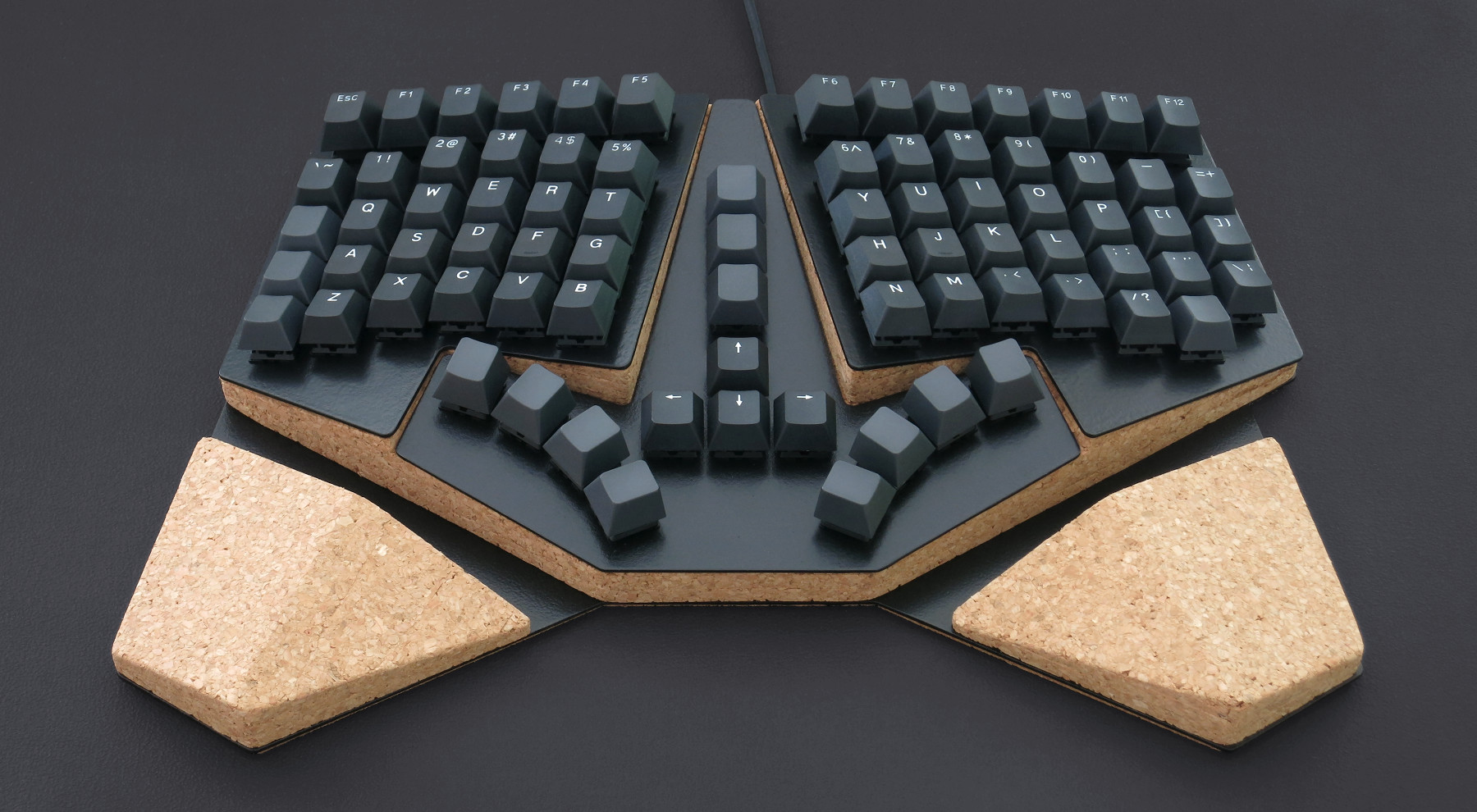
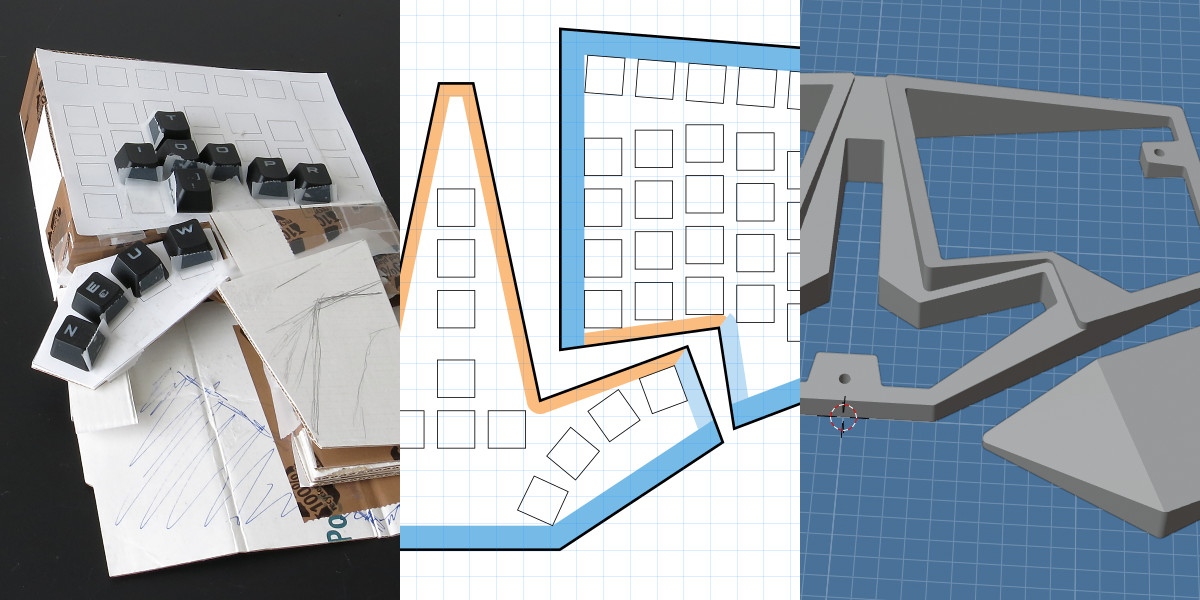
It all started with cardboard mockups and paper printouts, drawn in Inkscape. I settled on a layout with staggered columns, inspired by projects like the Ergodox, Redox, and Pteron.
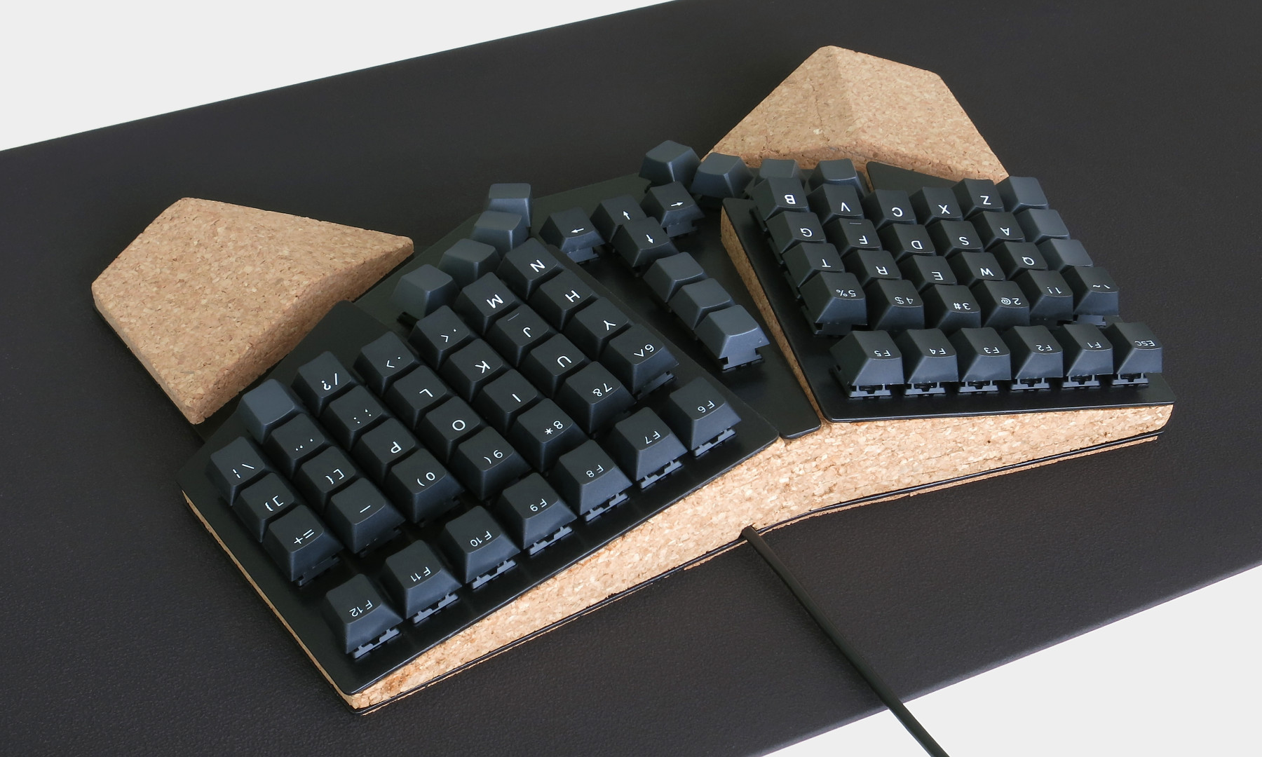
I rearranged the keys and abandoned symmetry in favor of an extra column on the right side, to stay closer to the standard ANSI layout. Also, the stagger is more pronounced and continuous for the little fingers, which seems more comfortable to me. Both sides are then raised to a tented position.
For the thumb clusters, my primary concern was to better match the movement and push angle of the thumbs. In particular, I did not want to keep the thumb keys on the same plane as the other keys, because that requires the thumbs to stretch upwards. I ended up with the concept of a separate middle piece, which can be angled independently.
Because the tenting requires a somewhat complex body shape, I intended to have it 3D-printed. However, I was concerned about the cost, as well as potential stability issues. Instead, I decided to use affordable and precise laser-cut aluminium plates, and glue them onto a 3D-hull made of layered cork. After all, cork is cheap, easy to work with, and commonly used as a dampening material.
Body
The body is designed with Blender. Once the plates were imported, angled, and positioned in 3D space, I projected them onto the z-plane to design the floor plan of the body, which could then be extruded vertically. All of this required a fair bit of manual editing, so ideally, this process could be automated with a tool like OpenSCAD.
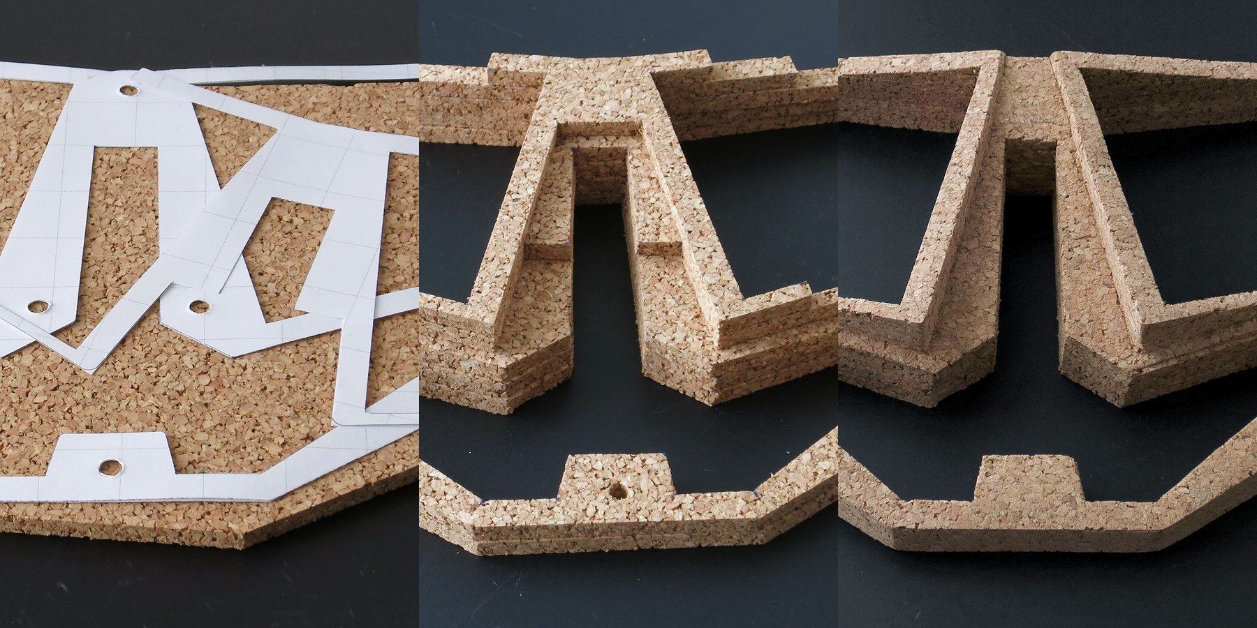
To accurately recreate the body out of cork, I sliced the STL model into layer outlines with a Python script, and printed them on paper. I also included grid lines in the prints, which turned out quite useful to calibrate the scaling. I then transferred the outlines to a 6 mm cork sheet and cut the layers with a box cutter, metal ruler, and a hole punch.
I then glued the layers on top of each other with waterproof and flexible glue. Finally, I cut off the stepping with the box cutter and sanded the outside of the body for a smooth finish. I was concerned that the cork would easily crumble, but it proved to be very resilient. Even the thinnest parts remained intact without issue.
To cut the plates from 1.5 mm aluminium, I converted the plate outlines to DXF files with another Python script and sent them to a laser-cutting service. Because they were charging per piece, I bridged the top plates together to decrease the cost. Afterwards, I cut the pieces apart with a metal saw, and cleaned them up with P120 and P240 sanding paper. To paint the surface, I applied a coat of suitable acrylic primer, followed by polyurethane acrylic paint. I used a simple foam roller to apply the paint, though next time I might try a good quality brush instead, for a smoother finish. I also will try to sand down the outside edges to a rounder bevel, so that the paint can cover them more evenly. Still, I'm quite pleased with the outcome of my first attempt.
Electronics
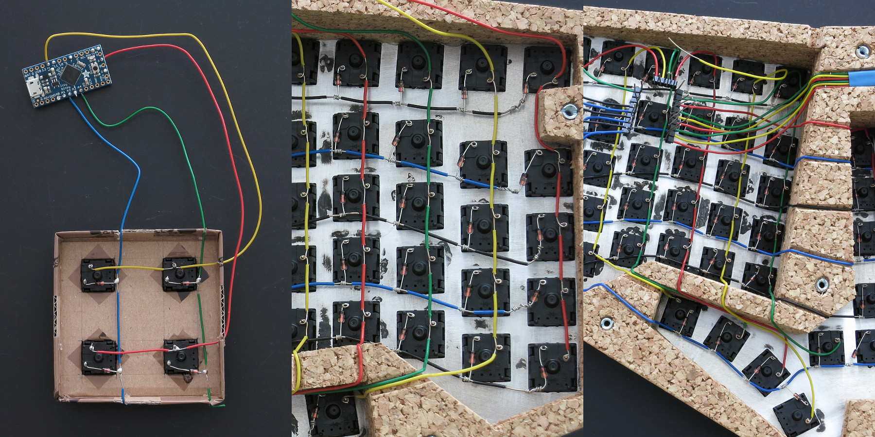
The electronics are hand-wired. I mostly followed existing guides, check out the QMK Hand-Wiring Guide for a good overview. In particular, I learned about the importance of the diodes from Dave Dribin. For practice, I implemented a simple 2x2 matrix.
To prepare for the wiring, I installed linear Cherry MX Silent Red switches, which snapped firmly into the plate cutouts. The top row is inserted upside down, so that the pins are more accessible. The switches are connected in a 14x6 matrix, with solid 0.5 mm (24 AWG) wire. To route the wires across the walls, I cut grooves into the cork, which looks a bit silly but works well. I removed the wire insulation with a box cutter, and spliced the wires and diodes together for solid connections. To hook up the controller board, I repurposed the plastic parts of pin headers, pushing the stripped wires through and bending them, so they are correctly spaced and held in place.
With all the wires in place, I soldered the connections using 0.5 mm (24 AWG) lead-free solder wire, an iron temperature of 340°C, and a 1.2 mm chisel tip. Thanks to all the splicing, the soldering was not particularly difficult. Though I applied a bit too much solder at times, so there is definitely room for improvement.
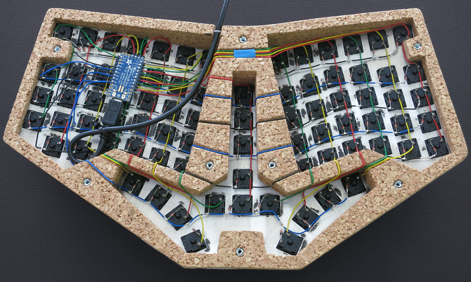
The processing and USB communication is performed on an Adafruit ItsyBitsy controller board, which offers plenty of IO pins and a solid USB micro-B socket. It is compatible with the Arduino ecosystem so that I could compile and install my own firmware with arduino-cli. Check out the firmware repository for more details.
Future
There are a couple of things I want do improve for the next version.
First, I'm not yet satisfied with the middle plate layout. Either I will remove one of the middle keys, to end up with an optimal 13x6 matrix. Or I may go full ham and add a dedicated numpad.
To further reduce costs, I will bridge all the plates for the laser-cutting, not just the top ones. The plates also should include some screw holes to securely mount the controller and USB cable. And I will glue a dampening layer on the underside of the top plates, to further reduce the typing sound.
Most importantly, I would like to experiment with different materials for the body, specifically with silicone.
This first prototype of Chrumm has turned out quite well and allowed me to get a feel for the actual typing experience. I have learned a lot, and I'm keen to work on the next iteration.