Another keyboard prototype
October 2020
After my experience with the first prototype of the Chrumm keyboard, I was eager to build the next iteration. As before, the project files are available on GitHub, along with the list of materials.
Revisions
Based on extended testing, I found a few issues with the initial design. Most importantly, it is too tall for comfort. Also, the thumb clusters are too crowded, especially the two lower keys on each side are difficult to hit accurately without looking.
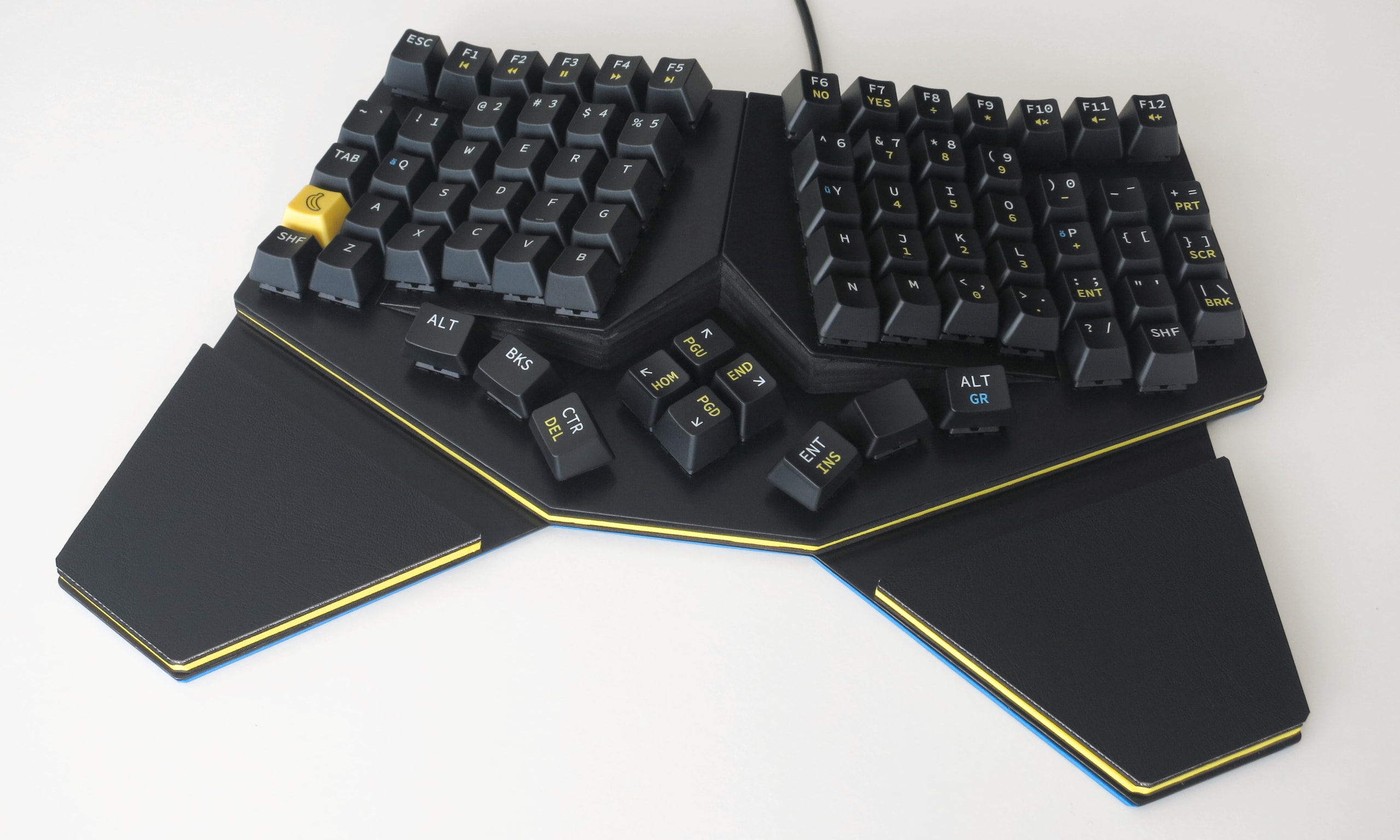
Consequently, I have fully redesigned the plates. Now the outer keys are placed on a horizontal rim, which reduces the overall height significantly. The tenting starts at the ring finger, which also creates a simplified concave shape. Yet it still consists of only three switch planes, so that it remains as simple as possible to design PCBs for it later.
In case of the thumb clusters, everything fell into place when I decided to reduce them to three keys per side. After all, I never use the left space or right Ctrl anyway. This opened up enough room to use 1.25u keycaps, which are more comfortable and easier to hit. To recreate the forward-facing angle, the the caps are placed upside-down.
Other changes include a more pronounced stagger for the little fingers, and the diamond arrangement of the arrow keys, to move the sides closer together.
Body
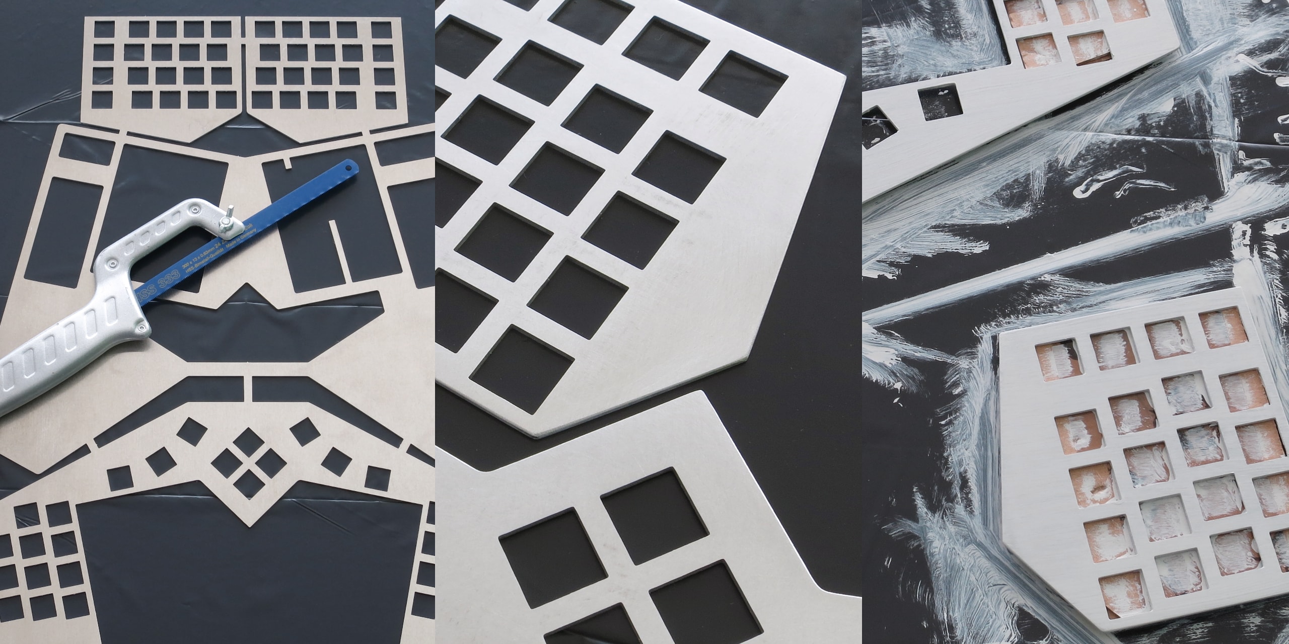
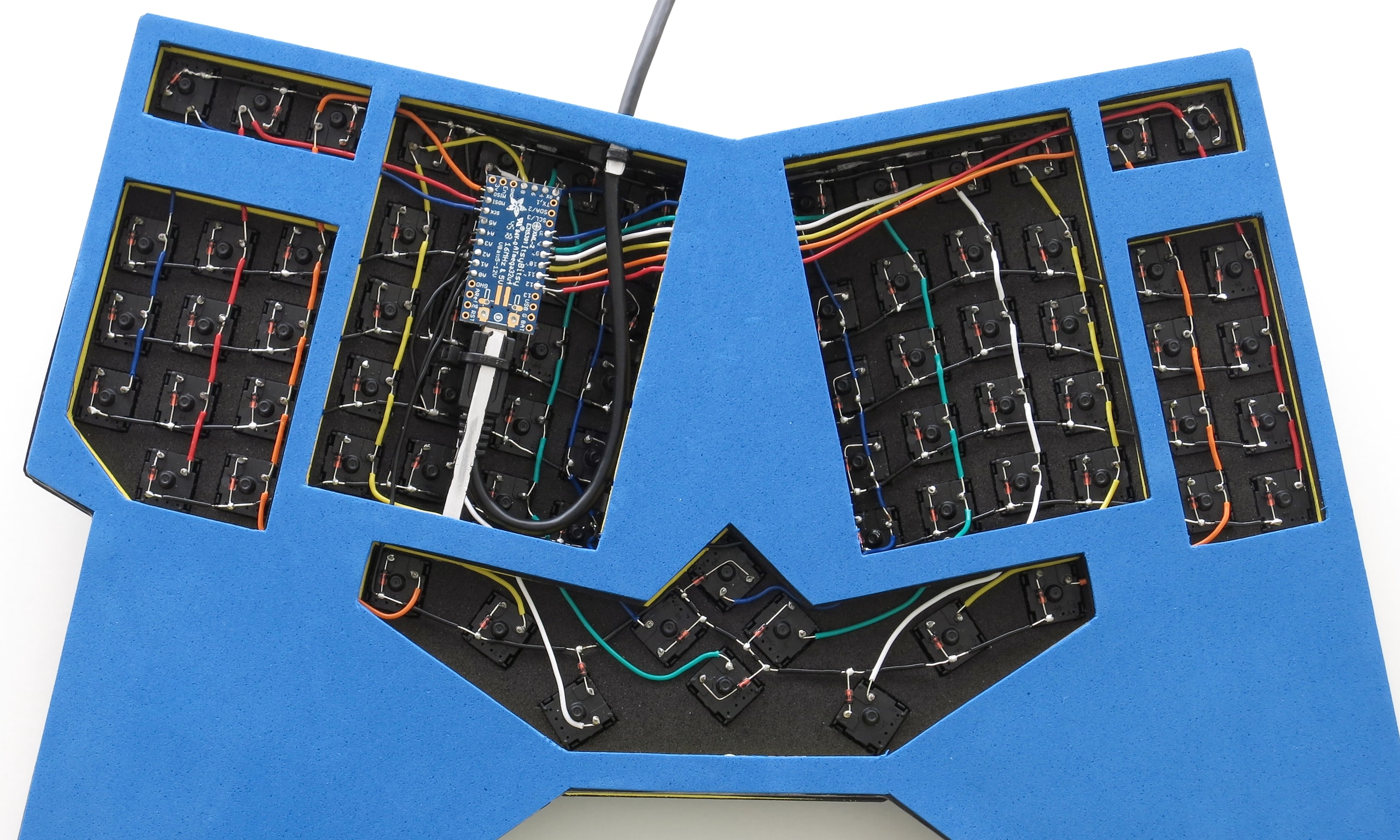
Similar to the first prototype, the body is sandwiched between 1.5 mm aluminium plates. I beveled the outer edges of the plates with sanding paper, and applied the primer and polyurethane acrylic paint with a brush. However, the brush strokes caused the paint to accumulate in the switch holes, which was rather cumbersome to clean up. After having tried both, I recommend a foam roller instead.
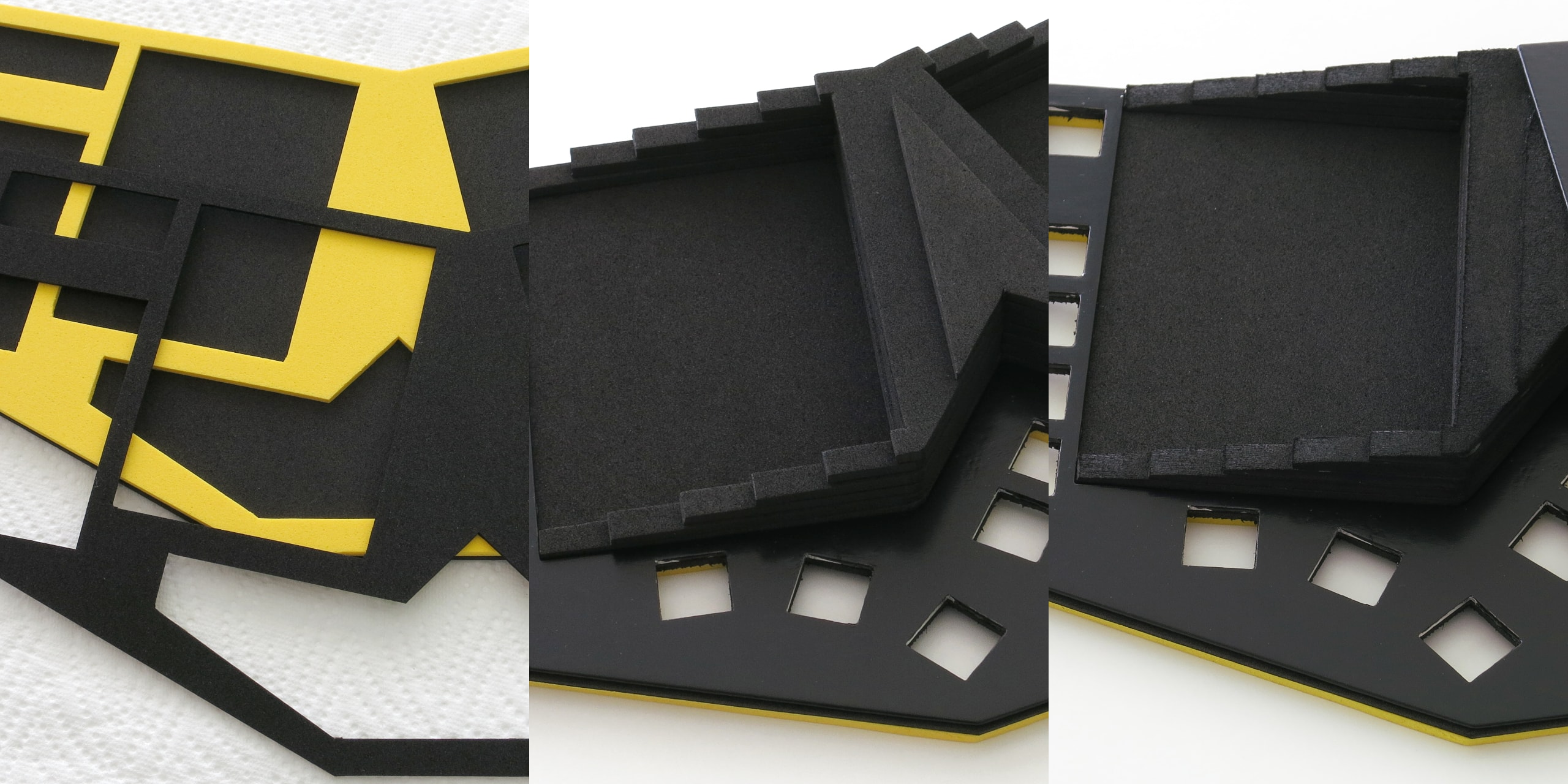
In an attempt to maximize the dampening and minimize the cost, I assembled the body out of EVA foam layers. The foam was surprisingly tear-resistant, I could even somewhat sand down the stepping with P120 sanding paper. So far, it is holding up well, though I don't know how long it will last. It does however provide better sound dampening than cork.
Wiring
The wires are routed through the middle foam layer, before the body was fully glued together. The switches are connected in a 13x6 matrix, with solid 0.5 mm (24 AWG) wire.
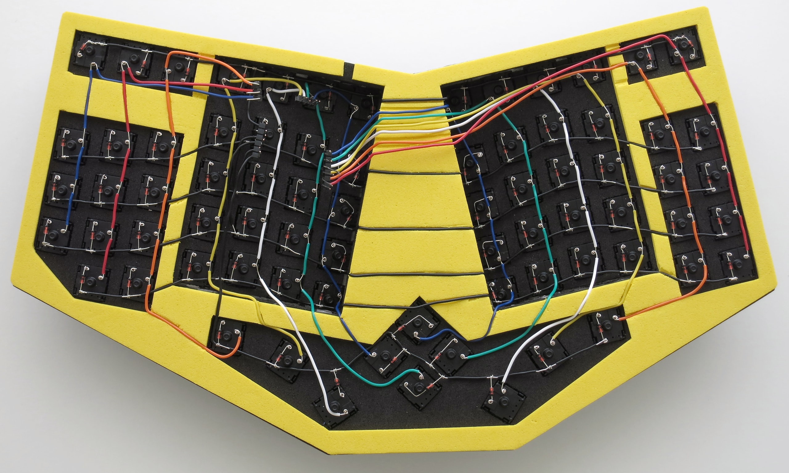
The underside is left open, because it was impossible to add any kind of threading to the foam, which would have allowed a plate to be screwed on. Conveniently, this made it possible to attach the USB cable directly to the bottom plate with zip ties, for extra yank-resistance. In turn, the Adafruit ItsyBitsy board is firmly held in place.
Caps
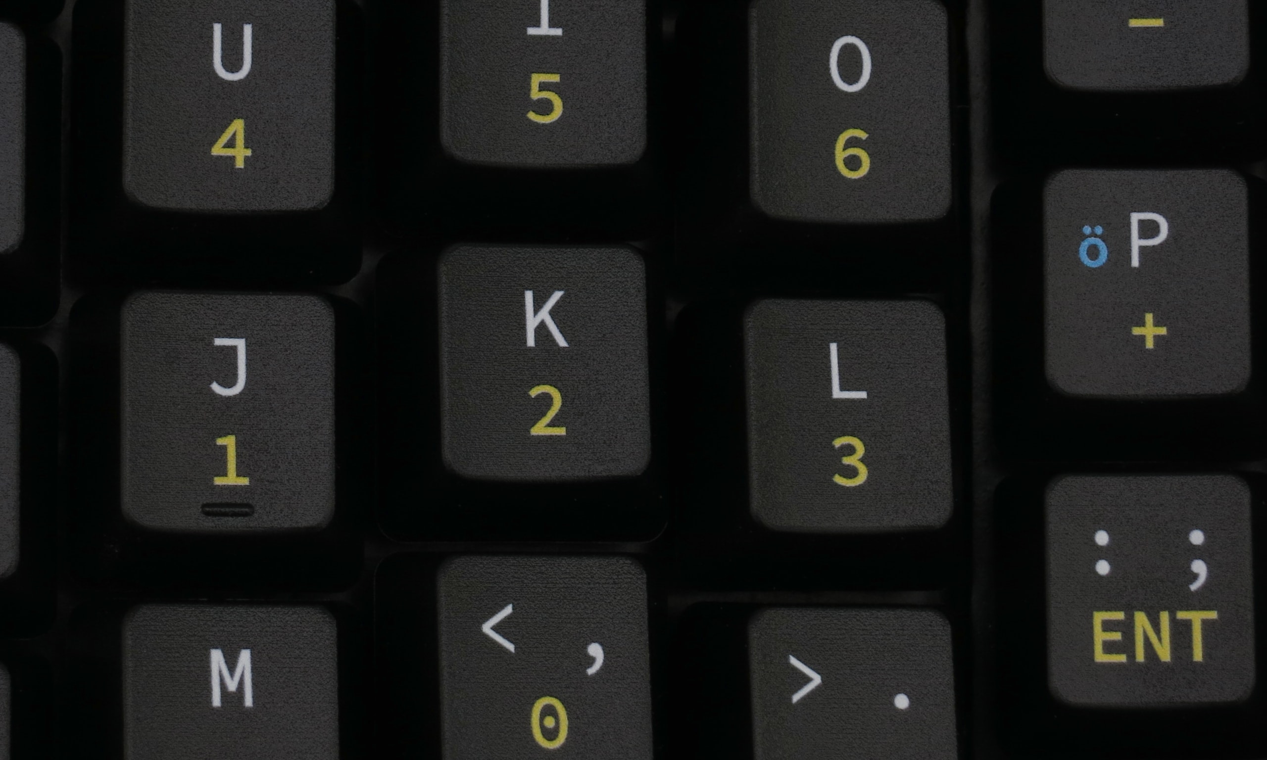
The keycaps can be sourced from a single tenkeyless (TKL) set, with a bit of improvisation. To better memorize the layout, I ordered a custom printed set from WASD. They are made of fairly thin ABS, but I don't mind.
The quality and resolution of the print is very nice. The colored letters are printed on top of a white base layer. From a normal viewing distance, I cannot see any color offset. The top surface of the caps is sealed with a clear coat. The coating has a subtle grainy texture, with faint horizontal grooves. I cannot say anything about their longevity, but so far, I consider the caps great value for money.
Future
Manually layering the body and wiring the switches is fairly cheap, and does not require specialized tools. However, it is a lot of work.
For the next version, I want to learn about 3D printing, and design a unified model with proper CAD tools. Thus it should get a lot easier for myself and others to build it.